sidenote

Archívum
A(z) „alkotunk” kategória bejegyzései

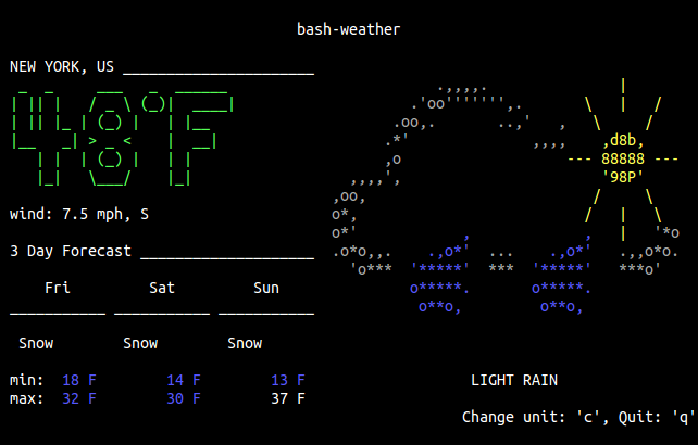
About a year ago I got a request on GitHub regarding bash-weather, if I intend to make bash-weather print a colored output. I totally forgot about it. But when the other day I was browsing on GitHub I remembered this request, and I have written the “colored output feature”.

bash-weather

bash-weather bash-weather bash-weather

Also, there are some videos about bash-weather and my previous shell scripts (bash-gorillas, bash-life) made by a guy who I think is really into command-line applications (I can understand why).

https://www.youtube.com/watch?v=EAbeSyAOtA4

Check out the description below the videos. ;)

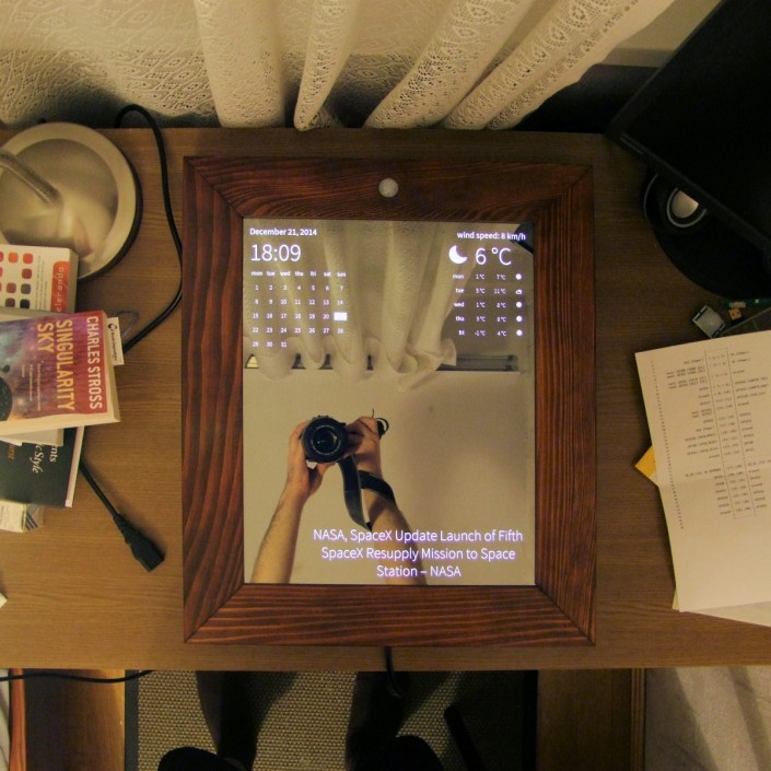
I have been working on a project since last (2014) spring. I have been building a mirror inspired by Michael Teeuw’s Magic Mirror and now I have finished it! It is called Mirror π, and it is a “smart mirror”.

Mirror π

What’s this all about? How is it smart? More posts to come (I hope sooner than later), until than you can already browse the source code on GitHub.

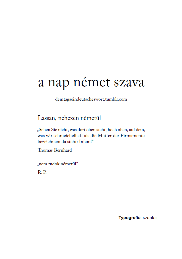
Múlt héten keresett meg egy kedves barátom, a nap német szava blog szerzője, hogy egy darabig leáll a blog írásával, de szeretné, ha a bejegyzések PDF-ben is elérhetők lennének.

Hát összeálltunk. Ő fogta és lementette az összes posztot. Nagyjából* arra a formára hozta az anyagot, amiben előre megegyeztünk. Én írtam egy parsert LuaTeX-ben. És megszületett a PDF változat.

Ha hibát találtok benne, kérlek jelezzétek!

Az amúgy is zseniális blog bejegyzései mostantól A5-ös méretben, nyomtatásra optimalizáltan** elérhetők:

a nap német szava

* Azért benne hagyott közel kétszáz helytelen idézőjelet, és húsz-harminc rosszul tördelt sort, de sebaj, csak két órát basztam el a kijavításukkal.

** Már ha ki fogsz nyomtatni több, mint hétszáz oldalt. Amúgy képernyőn is jól néz ki.

Another font outline animation experiment

In this animation was created using LuaTeX, TikZ, and the glyph “a” from the Linux Libertine font.

The process which this animation resulted in was the following:

  1. Converted the font to SVG to use the path of the glyph.
  2. Split the path into the inner and outer outlines.
  3. Draw the two separate lines with (different) dashed patterns.
  4. Set increasing offset for the dashed patterns for each frame.
  5. Rasterize and create GIF using GIMP.

Sorry, no source code this time.

In one of my latest posts I mentioned a question about how to draw individual glyphs with randomized paths on TeX.SX. Today I want to share the answer I posted about two weeks ago, and some related stuff which I’ve made during and after working on the answer.

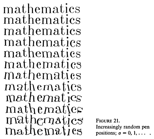
Let’s see the question first. It is quoting Donald Knuth’s article, Mathematical typography from the Bulletin of the American Mathematical Society.

Knuth: Mathematical typography, Figure 21

Randomization. I’d like to report on a little experiment I did with random numbers. One might complain that the letters I have designed are too perfect, too much like a computer, so they lack “character”. In order to counteract this, we can build a certain amount of randomness into the choices of where to put the pen when drawing each letter, and Figure 21 shows what happens. The coordinates of the key pen positions where chosen independently with a normal distribution and with increasing standard deviation, so that the third example has twice as much standard deviation as the second, the fourth has three times as much, and so on. Note that the two m’s on each line (except the first) are different, and so are the a’s and the t’s, since each letter is drawn randomly.

The question was how to achieve a similar effect in LaTeX without using MetaFont. You can read the answer below, but if you feel tl;dr skip below the long quote for my related works.

I have been thinking about this question for weeks now, and finally I think I came really close to a result you may also like. I have even tried to use Processing to solve this problem, which resulted in a nice animation as a byproduct, but it didn’t lead me closer to the solution. But back to the point…

Unfortunately the solution I’m posting, which is my best and only shot, does not support drawing the distorted glyphs as text but as drawings. Also there is some work to be done outside the context of LaTeX, but most of it is done in LaTeX (LuaTeX + TikZ).

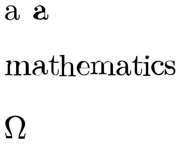
Randomized drawing of individual glyphs

The picture above shows an undistorted glyph (character “a” on the left in the line at the top), a distorted glyph (character “a” on the right in the line at the top), a word consisting of distorted glyphs (middle line), and a special character (Omega), all these can be found in the code at the end of the answer.

Now I will describe the process I have followed to achieve these distortions. I mentioned that there is some work to be done outside of LaTeX, that is to convert a font file into SVG using FontForge. I found the solution how to do this in an answer to the question: Can we extract the points making the character from the font file?

Copy the following into a file named font2svg.pe into your “project” folder.

1
2
3
#!/usr/bin/env fontforge
Open($1)
Generate($1:t:r + ".svg")

And make a SVG file from the font you want to use (I chose cmr10) with the following command.

fontforge font2svg.pe /usr/local/texlive/2014/texmf-dist/fonts/type1/public/amsfonts/cm/cmr10.pfb

Note that the location of the font on the filesystem may vary based on your LaTeX installation and operating system you use, but this will generate an SVG file into your project folder. All is left to process the generated SVG file which contains the data (name, unicode code, width, and outline) of the glyphs, which I will describe below.

The function function read_font_data(file) takes a file name as an argument (the generated SVG file), and extracts the data of the glyphs into an associative array which can be addressed with the unicode code and contains the width and outline data of the specific character. Note that not all glyphs have width or outline data, some basic error checking is done but the code is not foolproof.

The function random_in_interval(lower_boundary, upper_boundary) takes two float arguments, and will return a random float between them. The more the boundaries converge to 1 the smaller the randomization will be. This will be used when the time comes to randomize the outline of a glyph.

The function scale_and_randomize(glyph, scale_factor, lower_boundary, upper_boundary) will take a glyph, a scale factor, a lower and upper boundary, the latter two will be used for the randomization. Scaling is needed because the default measurement unit of TikZ is centimeters (I think) and the outline data of a glyph may contain large values, which TikZ interprets as centimeters. Note that the scale factor may vary depending the font you use, and size you want.

The functions print_glyph(glyph, scale_factor, lower_boundary, upper_boundary) and return_glyph (the latter takes the same arguments) only differ in that print_glyph will pass the TikZ drawing command (using svg.path library) used to print the glyph to LaTeX, while return_glyph only returns the drawing command as a string which can be further used in Lua before passing it to LaTeX.

The remaining functions only use the previously described print_glyph and return_glyph functions to print the picture above.

That’s it. I hope this would fit your needs.

1
2
3
4
5
6
7
8
9
10
11
12
13
14
15
16
17
18
19
20
21
22
23
24
25
26
27
28
29
30
31
32
33
34
35
36
37
38
39
40
41
42
43
44
45
46
47
48
49
50
51
52
53
54
55
56
57
58
59
60
61
62
63
64
65
66
67
68
69
70
71
72
73
74
75
76
77
78
79
80
81
82
83
84
85
86
87
88
89
90
91
92
93
94
95
96
97
98
99
100
101
102
103
104
105
106
107
108
109
110
111
112
113
114
115
116
117
118
119
120
121
122
123
124
125
126
127
128
129
130
131
132
133
134
135
136
137
138
139
140
141
142
143
144
145
146
147
148
149
150
151
152
153
154
155
156
157
158
159
160
161
162
163
164
165
166
167
168
169
170
171
172
173
174
175
176
177
178
179
180
181
182
183
184
185
186
187
188
189
190
191
192
193
194
195
196
197
198
199
200
201
202
203
204
205
206
207
208
209
210
211
212
213
214
215
216
217
218
219
220
221
222
223
224
225
226
227
228
229
230
231
% Randomized drawing of individual glyphs
% Author: István Szántai (szantaii)
% Original at: http://tex.stackexchange.com/a/197677/8844
\documentclass[10pt, a4paper]{article}

\usepackage[T1]{fontenc}

\usepackage{luacode}

\usepackage{tikz}
\usetikzlibrary{svg.path, positioning}

\pagestyle{empty}

\tikzset{%
    glyph node/.style={%
        inner sep=0pt,%
        outer sep=0pt%
    },%
    glyph outline/.style={%
        line width=0pt%
    }%
}

\begin{luacode*}
    function read_font_data(file)
        local glyphs = {}
        local fd = io.open(file, "r")
        local content = fd:read("*all")
        fd.close()
       
        for glyph in string.gmatch(content, "<glyph[^/>]*") do
            local glyph_tag = string.gsub(glyph, "\n", " ")
            local unicode = string.match(glyph_tag, "unicode="[^"]*")
            local outline = string.match(glyph_tag, "d="[^"]*")
            local width = string.match(glyph_tag, "horiz%-adv%-x="[^"]*")
           
            if unicode ~= nil and #unicode >= 10 then
                unicode = string.sub(unicode, 10, #unicode)
            end
           
            if outline ~= nil and #outline > 4 then
                outline = string.sub(outline, 4, #outline)
            end
           
            if width ~= nil and #width >= 14 then
                width = string.sub(width, 14, #width)
            end
           
            if unicode ~= nil then
                glyphs[unicode] = {width, outline}
            end
        end
       
        return glyphs
    end
   
    -- returns a random float number between the specified boundaries (floats)
    function random_in_interval(lower_boundary, upper_boundary)
        return ((math.random() * (upper_boundary - lower_boundary)) + lower_boundary)
    end
   
    -- note: scaling is applied before randomization
    function scale_and_randomize(glyph, scale_factor, lower_boundary, upper_boundary)
        local width = glyph[1]
        local outline = glyph[2]
       
        local previous_was_number = false
        local processed_outline = ""
        local number = ""
       
        if width ~= nil then
            width = width * scale_factor
        end
       
        if outline ~= nil then
            for i = 1, #outline, 1 do
                local char = string.sub(outline, i, i)
               
                if previous_was_number then
                    if string.match(char, '%d') ~= nil or
                        char == "." then
                        number = number .. char
                    else
                        -- scale and randomize
                        number = number * scale_factor
                        number = number * random_in_interval(lower_boundary, upper_boundary)
                        number = string.format("%.3f", number)
                        processed_outline = processed_outline .. number .. char
                        number = ""
                        previous_was_number = false
                    end
                else
                    if string.match(char, '%d') ~= nil or
                        char == "-" then
                       
                        number = number .. char
                        previous_was_number = true
                    else
                        processed_outline = processed_outline .. char
                        previous_was_number = false
                    end
                end
            end
        end
       
        return {width, processed_outline}
    end
   
    function print_glyph(glyph, scale_factor, lower_boundary, upper_boundary)
        local randomized_glyph = scale_and_randomize(glyph, scale_factor, lower_boundary, upper_boundary)
        local width = randomized_glyph[1]
        local outline = randomized_glyph[2]

        if outline ~= nil then
            tex.sprint("\\filldraw[glyph outline] svg "" .. outline .. "";")
        end
    end
   
    function return_glyph(glyph, scale_factor, lower_boundary, upper_boundary)
        local randomized_glyph = scale_and_randomize(glyph, scale_factor, lower_boundary, upper_boundary)
        local width = randomized_glyph[1]
        local outline = randomized_glyph[2]
       
        if outline ~= nil then
            return "\\filldraw[glyph outline] svg "" .. outline .. "";"
        else
            return ""
        end
    end
   
    function draw_sample_glyphs(glyphs)
        tex.sprint("\\begin{tikzpicture}")
        tex.sprint("\\node[glyph node, matrix, anchor=south west] (a1) {" ..
            return_glyph(glyphs["a"], 0.05, 1, 1) ..
            "\\\\};")
        tex.sprint("\\node[glyph node, matrix, anchor=south west, right=7.5mm of a1] (a2) {" ..
            return_glyph(glyphs["a"], 0.05, 0.8, 1.2) ..
            "\\\\};")
        tex.sprint("\\end{tikzpicture}")
    end
   
    function draw_sample_text(glyphs)
        local horizontal_space = "0.5mm"
        local vertical_space = "1.25mm"
        local scale = 0.05
        local lower_boundary = 0.9
        local upper_boundary = 1.1
       
        tex.sprint("\\begin{tikzpicture}")
        tex.sprint("\\node[glyph node, matrix] (m1) {" ..
            return_glyph(glyphs["m"], scale, lower_boundary, upper_boundary) ..
            "\\\\};")
       
        tex.sprint("\\node[glyph node, matrix, right=" .. horizontal_space ..
            " of m1] (a1) {" ..
            return_glyph(glyphs["a"], scale, lower_boundary, upper_boundary) ..
            "\\\\};")
       
        tex.sprint("\\node[glyph node, matrix, right=" .. horizontal_space ..
            " of a1] (t1) {" .. "\\raisebox{" .. vertical_space .. "}{" ..
            return_glyph(glyphs["t"], scale, lower_boundary, upper_boundary) ..
            "}" .. "\\\\};")
       
        tex.sprint("\\node[glyph node, matrix, right=" .. horizontal_space ..
            " of t1] (h1) {" .. "\\raisebox{" .. vertical_space .. "}{" ..
            return_glyph(glyphs["h"], scale, lower_boundary, upper_boundary) ..
            "}" .. "\\\\};")
       
        tex.sprint("\\node[glyph node, matrix, right=" .. horizontal_space ..
            " of h1] (e1) {" ..
            return_glyph(glyphs["e"], scale, lower_boundary, upper_boundary) ..
            "\\\\};")
       
        tex.sprint("\\node[glyph node, matrix, right=" .. horizontal_space ..
            " of e1] (m2) {" ..
            return_glyph(glyphs["m"], scale, lower_boundary, upper_boundary) ..
            "\\\\};")
       
        tex.sprint("\\node[glyph node, matrix, right=" .. horizontal_space ..
            " of m2] (a2) {" ..
            return_glyph(glyphs["a"], scale, lower_boundary, upper_boundary) ..
            "\\\\};")
       
        tex.sprint("\\node[glyph node, matrix, right=" .. horizontal_space ..
            " of a2] (t2) {" .. "\\raisebox{" .. vertical_space .. "}{" ..
            return_glyph(glyphs["t"], scale, lower_boundary, upper_boundary) ..
            "}" .. "\\\\};")
       
        tex.sprint("\\node[glyph node, matrix, right=" .. horizontal_space ..
            " of t2] (i1) {" .. "\\raisebox{" .. vertical_space .. "}{" ..
            return_glyph(glyphs["i"], scale, lower_boundary, upper_boundary) ..
            "}" .. "\\\\};")
       
        tex.sprint("\\node[glyph node, matrix, right=" .. horizontal_space ..
            " of i1] (c1) {" ..
            return_glyph(glyphs["c"], scale, lower_boundary, upper_boundary) ..
            "\\\\};")
       
        tex.sprint("\\node[glyph node, matrix, right=" .. horizontal_space ..
            " of c1] (s1) {" ..
            return_glyph(glyphs["s"], scale, lower_boundary, upper_boundary) ..
            "\\\\};")
        tex.sprint("\\end{tikzpicture}")
    end
   
    function draw_sample_glyph(glyphs)
        tex.sprint("\\begin{tikzpicture}")
        print_glyph(glyphs["&#x3a9;"], 0.05, 0.95, 1.05)
        tex.sprint("\\end{tikzpicture}")
    end
   
    function main()
        local cmr10_glyphs = {}
       
        math.randomseed(os.time())
       
        cmr10_glyphs = read_font_data("cmr10.svg")
       
        tex.sprint("\\noindent")
        draw_sample_glyphs(cmr10_glyphs)
        tex.sprint("\\\\[2cm]")
        draw_sample_text(cmr10_glyphs)
        tex.sprint("\\\\[2cm]")
        draw_sample_glyph(cmr10_glyphs)
    end
\end{luacode*}

\begin{document}
\luadirect{main()}
\end{document}

Nice, isn’t it?

I’ve created an animation in LaTeX (clarification later) using this code, which makes the letter “a” wibbly-wobbly. There is also a video which shows the same letter but only the outline is drawn, but in my opinion it doesn’t look that good: Glyph distortion – YouTube.

https://www.youtube.com/watch?v=qd7i83b6DjI

These videos are also available on Vimeo: Glyph distortion on Vimeo, Glyph distortion #2 on Vimeo.

The second animation (also made in LaTeX) draws a big letter “a” stacking only outlines of it on top of each other which it gives a hollow like look.

https://www.youtube.com/watch?v=eTM3fKI5W6Y

This video is also available on Vimeo: Font outline animation #2 on Vimeo.

Only one question remains, how did I made these animations in LaTeX? I just built upon the code above, and rendered a long PDF which’s each page is a frame of the animation. After that I only followed some steps I’ve described before.

https://www.youtube.com/watch?v=NpCqjrXWzuQ

The video is also available on Vimeo.

This animation is strongly connected to LaTeX. How come? – you could ask. I’ll come to the point but first I have to confess that this nice piece of video/animation/whatever is “only” a byproduct of a search for a LaTeX related answer.

I’m a LaTeX enthusiast, and I’m trying to be active on TeX.SX, and found a question about how to draw individual glyphs with randomized paths which I could not stop thinking about. I even wanted to learn Metapost, but when I saw what was laying before me I was intimidated. So I thought I should try something easier first, namely Processing, which was very useful for some small projects in the past. I found the Geomerative library written by Ricard Marxer, and when I was looking into the examples which came with the library I found an interesting one, which used the vertices of font outlines. Then came the idea that it would be nice to try to polygonize individual glyphs with different accuracy, draw Bézier curves along/through the vertices, and stack these images on top each other. Just to see how it looks. In the end it turned out to be pretty awesome, I think.

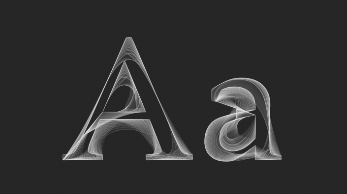
Font outline animation

I’m sharing the source with some notes what and how it does what it does, so others may come up with nice things too. But if you don’t want the “magic” to be debunked, this is where you should stop reading this post.

Note that the following source code comes with no warranty at all, and is under the CC BY-NC-SA 2.5 license.

1
2
3
4
5
6
7
8
9
10
11
12
13
14
15
16
17
18
19
20
21
22
23
24
25
26
27
28
29
30
31
32
33
34
35
36
37
38
39
40
41
42
43
44
45
46
47
48
49
50
51
52
53
54
55
56
57
58
59
60
61
62
63
64
65
66
67
68
69
70
71
72
73
74
75
76
77
78
79
80
81
82
83
84
85
86
87
88
89
90
91
92
93
94
95
96
97
98
99
100
101
102
103
104
105
106
107
108
109
110
111
112
113
114
115
116
117
118
119
120
121
122
123
124
125
126
/*
Font outline animation
Author: István Szántai (szantaii)
License: CC BY-NC-SA 2.5
*/

import geomerative.*;
import processing.pdf.*;

int frameCount;
float backgroundColor;
float strokeColor;
float strokeOpacity;
float fadeOutOpacity;
float fadeOutOpacityStep;
RShape shape;
RPoint[] points;
int initialPolygonizerLength;
int currentPolygonizerLength;


void setup()
{
  frameCount = 0;
  backgroundColor = 38.25;
  strokeColor = 229.5;
  strokeOpacity = 25.5;
  fadeOutOpacityStep = 10.625;
  fadeOutOpacity = fadeOutOpacityStep;
 
  size(1280, 720, PDF, "frames.pdf");
 
  RG.init(this);

  initialPolygonizerLength = 179;
  currentPolygonizerLength = initialPolygonizerLength;
 
  print("Drawing...");
 
  smooth();
}

void draw()
{
  PGraphicsPDF pdf = (PGraphicsPDF) g;
 
  if (frameCount < 45)
  {
    background(backgroundColor);
    pdf.nextPage();
  }
  else if (frameCount < 399)
  {
    background(backgroundColor);
    noFill();
    strokeCap(ROUND);
    strokeJoin(ROUND);
    stroke(strokeColor, strokeOpacity);
 
    drawBezierVertices("A", width / 2 - 180, 4.95 * height / 6);
    drawBezierVertices("a", width / 2 + 230, 4.95 * height / 6);
   
    if (currentPolygonizerLength > 0)
    {
      --currentPolygonizerLength;
    }
   
    if (frameCount >= 375)
    {
        noStroke();
        fill(backgroundColor, fadeOutOpacity);
        rect(0, 0, 1280, 720);
        fadeOutOpacity += fadeOutOpacityStep;
    }
   
    pdf.nextPage();
  }
  else if (frameCount < 429)
  {
    background(backgroundColor);
    if (frameCount != 428)
    {
      pdf.nextPage();
    }
  }
  else
  {
    println(" done.");
    exit();
  }
 
  frameCount++;
}

void drawBezierVertices(String text, float horizontalPos, float verticalPos)
{
  shape = RG.getText(text, "Palatino-Roman.ttf", 650, CENTER);
  pushMatrix();
  translate(horizontalPos, verticalPos);
 
  for (int i = initialPolygonizerLength; i >= currentPolygonizerLength; i--)
  {
    RG.setPolygonizer(RG.UNIFORMLENGTH);
    RG.setPolygonizerLength(i);
    points = shape.getPoints();
   
    if(points != null && points.length > 3)
    {
      beginShape();
      for(int j = 0; j < points.length - 3; j++)
      {
        if (j == 0)
        {
          vertex(points[j].x, points[j].y);
        }
        else
        {
          bezierVertex(points[j].x, points[j].y,
            points[j + 1].x, points[j + 1].y,
            points[j + 2].x, points[j + 2].y);
        }
      }
      endShape();
    }
  }
  popMatrix();
}

The most important stuff is in the definition of the drawBezierVertices function. This is how it works. It gets a piece of text, which will be “written” with a defined font (note that the chosen font should be in the project’s data folder) making a shape, but it won’t be drawn to the screen. Instead the shape will be polygonized and through the calculated vertices a bezier curve will be drawn. This is iterated a couple times (180 times in this specific example) while vertices are getting closer to each other, so at the end a the true outline of the font would be drawn (more or less).

By reading the source you can also see that every frame of the animation is rendered to pages of a PDF document. Here is why. When rendering to PDF Processing will create a vectorized output. So in the end you can get the frames from the PDF in any resolution you want without losing quality. All is left to rasterize every page of the rendered PDF with the desired resolution into individual raster images (PNG files if you ask me), and make a video from the created image sequence.

Some practical advice. I’ve used Gimp to rasterize the pages of the PDF output (with FullHD, 1920×1080 resolution), and saved them as separate files using the Export Layers plugin. After that I made the image sequence into a video from the command-line using FFmpeg.

ffmpeg -r 30 -i %03d.png -c:v libx264 -preset veryslow -qp 0 -g 1 -bf 2 font_animation.mp4

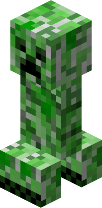
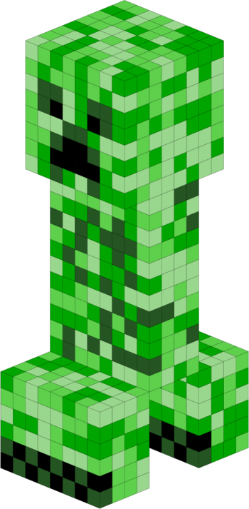
As a follow-up for my last post hereby I present a Creeper (right) in (Lua)LaTeX.

Creeper Creeper

Image source (left): File:Creeper.png – Minecraft Wiki

1
2
3
4
5
6
7
8
9
10
11
12
13
14
15
16
17
18
19
20
21
22
23
24
25
26
27
28
29
30
31
32
33
34
35
36
37
38
39
40
41
42
43
44
45
46
47
48
49
50
51
52
53
54
55
56
57
58
59
60
61
62
63
64
65
66
67
68
69
70
71
72
73
74
75
76
77
78
79
80
81
82
83
84
85
86
87
88
89
90
91
92
93
94
95
96
97
98
99
100
101
102
103
104
105
106
107
108
109
110
111
112
113
114
115
116
117
118
119
120
121
122
123
124
125
126
127
128
129
130
131
132
133
134
135
136
137
138
139
140
141
142
143
144
145
146
147
148
149
150
151
152
153
154
155
156
157
158
159
160
161
162
163
164
165
166
167
168
169
170
171
172
173
174
175
176
177
178
179
180
181
182
183
184
185
186
187
188
189
190
191
192
193
194
195
196
197
198
199
200
201
202
203
204
205
206
207
208
209
210
211
212
213
214
215
216
217
218
219
220
221
222
223
224
225
226
227
228
229
230
231
232
233
234
235
236
237
238
239
240
241
242
243
244
245
246
247
% Creeper
% Author: István Szántai (szantaii)
\documentclass{article}

\usepackage{luacode}

\usepackage{xcolor}

\usepackage{tikz}
\usepackage{tikz-3dplot}

\usepackage[active, tightpage]{preview}
\PreviewEnvironment{tikzpicture}
\setlength{\PreviewBorder}{1cm}

\definecolor{creeper_white}{HTML}{9AD78E}
\definecolor{creeper_lightgreen}{HTML}{5ED04C}
\definecolor{creeper_green}{HTML}{00A500}
\definecolor{creeper_darkgreen}{HTML}{255522}

\begin{luacode*}
    function draw_coordinate_system()
        tex.sprint("\\draw[white!50!gray,thick,->] (0,0,0) -- " ..
            "(3,0,0) node[text=white!50!gray,anchor=north east]{$x$};")
        tex.sprint("\\draw[white!50!gray,thick,->] (0,0,0) -- " ..
            "(0,3,0) node[text=white!50!gray,anchor=west]{$y$};")
        tex.sprint("\\draw[white!50!gray,thick,->] (0,0,0) -- " ..
            "(0,0,3) node[text=white!50!gray,anchor=south]{$z$};")
    end
   
    function matrix_scalar_multiplication(matrix, scalar)
        local rows = #matrix
        local cols = #matrix[1]
        local tmp_matrix = {}
       
        for i = 1, rows do
            tmp_matrix[i] = {}
            for j = 1, cols do
                tmp_matrix[i][j] = matrix[i][j] * scalar
            end
        end
       
        return tmp_matrix
    end
   
    function shift_coordinates(matrix, array)
        local matrix_rows = #matrix
        local matrix_cols = #matrix[1]
        local array_length = #array
        local tmp_matrix = {}
       
        if matrix_cols == array_length then
            for i = 1, matrix_rows do
                tmp_matrix[i] = {}
                for j = 1, matrix_cols do
                    tmp_matrix[i][j] = matrix[i][j] + array[j]
                end
            end
           
            return tmp_matrix
        else
            return nil
        end
    end
   
    function tikzcube(x, y, z, color)
        local side_1 = {{1, 1, -1},
            {-1, 1, -1},
            {-1, -1, -1},
            {1, -1, -1}}
        local side_2 = {{-1, 1, -1},
            {-1, 1, 1},
            {-1, -1, 1},
            {-1, -1, -1}}
        local side_3 = {{-1, -1, -1},
            {1, -1, -1},
            {1, -1, 1},
            {-1, -1, 1}}
        local side_4 = {{1, 1, -1},
            {-1, 1, -1},
            {-1, 1, 1},
            {1, 1, 1}}
        local side_5 = {{1, -1, -1},
            {1, 1, -1},
            {1, 1, 1},
            {1, -1, 1}}
        local side_6 = {{1, 1, 1},
            {-1, 1, 1},
            {-1, -1, 1},
            {1, -1, 1}}
        local cube_sides = {side_1, side_2, side_3, side_4, side_5, side_6}
        local tex_cube = ""
       
        for i = 1, #cube_sides do
            tex_cube = tex_cube .. "\\draw[ultra thin, fill=" .. color .. "] "
           
            local current_side = matrix_scalar_multiplication(cube_sides[i], 0.5)
            current_side = shift_coordinates(current_side, {x, y, z})
           
            local current_side_rows = #current_side
            local current_side_cols = #current_side[1]
           
            for j = 1, current_side_rows do
                for k = 1, current_side_cols do
                    if k == 1 then
                        tex_cube = tex_cube .. "("
                    end
                   
                    tex_cube = tex_cube .. current_side[j][k]
                   
                    if k ~= current_side_cols then
                        tex_cube = tex_cube .. ", "
                    else
                        tex_cube = tex_cube .. ") -- "
                    end
                end
            end
           
            tex_cube = tex_cube .. "cycle;"
           
        end
       
        tex.sprint(tex_cube)
    end
   
    function draw_head(x_pos, y_pos, z_pos, colors_array)
        for x = x_pos, x_pos + 7, 1 do
            for y = y_pos, y_pos + 7, 1 do
                for z = z_pos, z_pos + 7, 1 do
                    if x == x_pos or x == x_pos + 7 or
                        y == y_pos or y == y_pos + 7 or
                        z == z_pos or z == z_pos + 7 then
                       
                        local color_index = math.random(1, #colors_array - 1)
                        tikzcube(x, y, z, colors_array[color_index])
                       
                        if x == x_pos + 7 and
                            (z == z_pos + 4 and
                            (y == y_pos + 2 or y == y_pos + 5)) or
                            (z == z_pos + 2 and
                            (y == y_pos + 3 or y == y_pos + 4)) or
                            (z == z_pos + 1 and
                            (y > 1 and y < 6)) then
                           
                            tikzcube(x, y, z, "black")
                        end
                       
                        if x == x_pos + 7 and
                            ((z == z_pos + 5 and
                            ((y > y_pos and y < y_pos + 3) or
                            (y > y_pos + 4 and y < y_pos + 7))) or
                            (z == z_pos + 4 and
                            (y == y_pos + 1 or y == y_pos + 6)) or
                            (z == z_pos + 3 and
                            (y == y_pos + 3 or y == y_pos + 4)) or
                            (z == z_pos + 2 and
                            (y == y_pos + 2 or y == y_pos + 5)) or
                            (z == z_pos and
                            (y == y_pos + 2 or y == y_pos + 5))) then
                           
                            tikzcube(x, y, z, colors_array[#colors_array])
                        end
                    end
                end
            end
        end
    end
   
    function draw_leg(x_pos, y_pos, z_pos, colors_array)
        for x = x_pos, x_pos + 3, 1 do
            for y = y_pos, y_pos + 7, 1 do
                for z = z_pos, z_pos + 5, 1 do
                    if x == x_pos or x == x_pos + 3 or
                        y == y_pos or y == y_pos + 7 or
                        z == z_pos or z == z_pos + 5 then
                       
                        local color_index = math.random(1, #colors_array - 1)
                        tikzcube(x, y, z, colors_array[color_index])
                       
                        if x == x_pos + 3 and
                            ((z == z_pos + 1 and
                            (y == y_pos or y == y_pos + 2 or
                            y == y_pos + 4 or y == y_pos + 6)) or
                            (z == z_pos and
                            (y == y_pos + 1 or y == y_pos + 3 or
                            y == y_pos + 5 or y == y_pos + 7))) then
                           
                            tikzcube(x, y, z, colors_array[#colors_array])
                        end
                       
                        if x == x_pos + 3 and
                            ((z == z_pos + 1 and
                            (y == y_pos + 1 or y == y_pos + 3 or
                            y == y_pos + 5 or y == y_pos + 7)) or
                            (z == z_pos and
                            (y == y_pos or y == y_pos + 2 or
                            y == y_pos + 4 or y == y_pos + 6))) then
                           
                            tikzcube(x, y, z, "black")
                        end
                    end
                end
            end
        end
    end
   
    function draw_bodypart(x_pos, y_pos, z_pos, x_length, y_length, z_length, colors_array)
        local color
        for x = x_pos, x_pos + x_length - 1, 1 do
            for y = y_pos, y_pos + y_length - 1, 1 do
                for z = z_pos, z_pos + z_length - 1, 1 do
                    if x == x_pos or x == x_pos + x_length - 1 or
                        y == y_pos or y == y_pos + y_length - 1 or
                        z == z_pos or z == z_pos + z_length - 1 then
                       
                        local color_index = math.random(1, #colors_array)
                        tikzcube(x, y, z, colors_array[color_index])
                    end
                end
            end
        end
    end
   
    function draw_creeper(x_rotation, z_rotation)
        local creeper_colors = {"creeper_white",
            "creeper_lightgreen",
            "creeper_green",
            "creeper_darkgreen"}
       
        tex.sprint("\\tdplotsetmaincoords{" .. x_rotation .. "}{" .. z_rotation .. "}")
        tex.sprint("\\begin{tikzpicture}[tdplot_main_coords]")
       
        math.randomseed(os.time())
       
        draw_leg(-2, 0, -18, creeper_colors)
        draw_leg(6, 0, -18, creeper_colors)
        draw_bodypart(2, 0, -12, 4, 8, 12, creeper_colors)
        draw_head(0, 0, 0, creeper_colors)
        -- draw_coordinate_system()
       
        tex.sprint("\\end{tikzpicture}")
    end
\end{luacode*}

\begin{document}
\luadirect{draw_creeper(66, 135)}
\end{document}

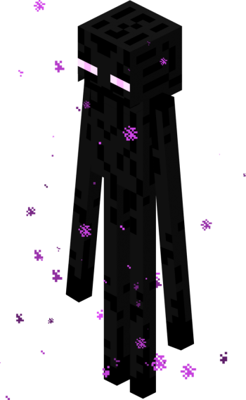
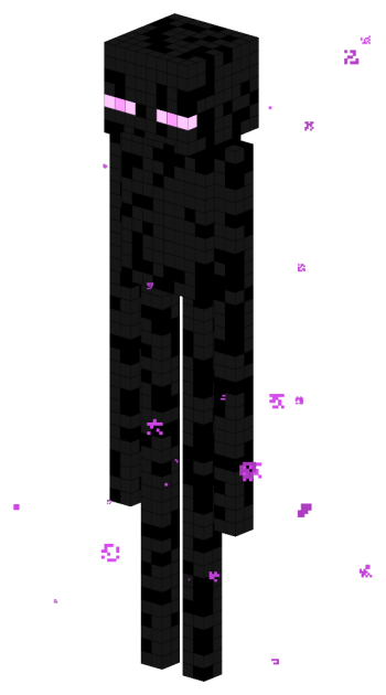
In the last couple of months I’ve watched some videos of Achievement Hunter’s Let’s Play Minecraft videos where were some encounters with Endermen. I was really fascinated by these creatures since they can teleport, demand respect, mysterious, etc.

I have been “playing” with LaTeX, especially with LuaTeX, recently, and I wanted to make a 3D-like picture. So I have chosen tikz‑3dplot and LuaTeX to draw an Enderman. (I think this is totally drawable with pure TikZ (syntax), therefore compilable with pdflatex, etc., but I found making this using LuaTeX much more simple.)

Enderman Enderman

Image source (left): File:Enderman normal.png – Minecraft Wiki

My drawing (right) is not accurate by many aspects, but I’ve achieved what I wanted.

1
2
3
4
5
6
7
8
9
10
11
12
13
14
15
16
17
18
19
20
21
22
23
24
25
26
27
28
29
30
31
32
33
34
35
36
37
38
39
40
41
42
43
44
45
46
47
48
49
50
51
52
53
54
55
56
57
58
59
60
61
62
63
64
65
66
67
68
69
70
71
72
73
74
75
76
77
78
79
80
81
82
83
84
85
86
87
88
89
90
91
92
93
94
95
96
97
98
99
100
101
102
103
104
105
106
107
108
109
110
111
112
113
114
115
116
117
118
119
120
121
122
123
124
125
126
127
128
129
130
131
132
133
134
135
136
137
138
139
140
141
142
143
144
145
146
147
148
149
150
151
152
153
154
155
156
157
158
159
160
161
162
163
164
165
166
167
168
169
170
171
172
173
174
175
176
177
178
179
180
181
182
183
184
185
186
187
188
189
190
191
192
193
194
195
196
197
198
199
200
% Enderman
% Author: István Szántai (szantaii)
\documentclass{article}

\usepackage{luacode}

\usepackage{xcolor}

\usepackage{tikz}
\usepackage{tikz-3dplot}

\usepackage[active, tightpage]{preview}
\PreviewEnvironment{tikzpicture}
\setlength{\PreviewBorder}{1cm}

\definecolor{endermanblack}{HTML}{000000}
\definecolor{endermangray}{HTML}{161616}
%\definecolor{endermanpurple}{HTML}{CC00FA}
%\definecolor{endermanlightpurple}{HTML}{E079FA}
\definecolor{endermanpurple}{HTML}{FF9EFF}
\definecolor{endermanlightpurple}{HTML}{FFC9FF}
\definecolor{particlecolor}{HTML}{DF4AF8}

\begin{luacode*}
    function draw_coordinate_system()
        tex.sprint("\\draw[white!50!gray,thick,->] (0,0,0) -- " ..
            "(3,0,0) node[text=white!50!gray,anchor=north east]{$x$};")
        tex.sprint("\\draw[white!50!gray,thick,->] (0,0,0) -- " ..
            "(0,3,0) node[text=white!50!gray,anchor=west]{$y$};")
        tex.sprint("\\draw[white!50!gray,thick,->] (0,0,0) -- " ..
            "(0,0,3) node[text=white!50!gray,anchor=south]{$z$};")
    end
   
    function tikzcube(x, y, z, color)
        --[[
        \draw[fill=red] (0.5, 0.5, -0.5) -- (-0.5, 0.5, -0.5) -- (-0.5, -0.5, -0.5) -- (0.5, -0.5, -0.5) -- cycle;
        \draw[fill=red] (-0.5, 0.5, -0.5) -- (-0.5, 0.5, 0.5) -- (-0.5, -0.5, 0.5) -- (-0.5, -0.5, -0.5) -- cycle;
        \draw[fill=red] (-0.5, -0.5, -0.5) -- (0.5, -0.5, -0.5) -- (0.5, -0.5, 0.5) -- (-0.5, -0.5, 0.5) -- cycle;
        \draw[fill=red] (0.5, 0.5, -0.5) -- (-0.5, 0.5, -0.5) -- (-0.5, 0.5, 0.5) -- (0.5, 0.5, 0.5) -- cycle;
        \draw[fill=red] (0.5, -0.5, -0.5) -- (0.5, 0.5, -0.5) -- (0.5, 0.5, 0.5) -- (0.5, -0.5, 0.5) -- cycle;
        \draw[fill=red] (0.5, 0.5, 0.5) -- (-0.5, 0.5, 0.5) -- (-0.5, -0.5, 0.5) -- (0.5, -0.5, 0.5) -- cycle;
        ]]

        local cube = ""
       
        cube = cube .. "\\draw[ultra thin, fill=" .. color .. "]" ..
            "(0.5 + " .. x .. ", 0.5 + " .. y .. ", -0.5 + " .. z .. ") -- " ..
            "(-0.5 + " .. x .. ", 0.5 + " .. y .. ", -0.5 + " .. z .. ") -- " ..
            "(-0.5 + " .. x .. ", -0.5 + " .. y .. ", -0.5 + " .. z .. ") -- " ..
            "(0.5 + " .. x .. ", -0.5 + " .. y .. ", -0.5 + " .. z .. ") -- cycle;"
        cube = cube .. "\\draw[ultra thin, fill=" .. color .. "]" ..
            "(-0.5 + " .. x .. ", 0.5 + " .. y .. ", -0.5 + " .. z .. ") -- " ..
            "(-0.5 + " .. x .. ", 0.5 + " .. y .. ", 0.5 + " .. z .. ") -- " ..
            "(-0.5 + " .. x .. ", -0.5 + " .. y .. ", 0.5 + " .. z .. ") -- " ..
            "(-0.5 + " .. x .. ", -0.5 + " .. y .. ", -0.5 + " .. z .. ") -- cycle;"
        cube = cube .. "\\draw[ultra thin, fill=" .. color .. "]" ..
            "(-0.5 + " .. x .. ", -0.5 + " .. y .. ", -0.5 + " .. z .. ") -- " ..
            "(0.5 + " .. x .. ", -0.5 + " .. y .. ", -0.5 + " .. z .. ") -- " ..
            "(0.5 + " .. x .. ", -0.5 + " .. y .. ", 0.5 + " .. z .. ") -- " ..
            "(-0.5 + " .. x .. ", -0.5 + " .. y .. ", 0.5 + " .. z .. ") -- cycle;"
        cube = cube .. "\\draw[ultra thin, fill=" .. color .. "]" ..
            "(0.5 + " .. x .. ", 0.5 + " .. y .. ", -0.5 + " .. z .. ") -- " ..
            "(-0.5 + " .. x .. ", 0.5 + " .. y .. ", -0.5 + " .. z .. ") -- " ..
            "(-0.5 + " .. x .. ", 0.5 + " .. y .. ", 0.5 + " .. z .. ") -- " ..
            "(0.5 + " .. x .. ", 0.5 + " .. y .. ", 0.5 + " .. z .. ") -- cycle;"
        cube = cube .. "\\draw[ultra thin, fill=" .. color .. "]" ..
            "(0.5 + " .. x .. ", -0.5 + " .. y .. ", -0.5 + " .. z .. ") -- " ..
            "(0.5 + " .. x .. ", 0.5 + " .. y .. ", -0.5 + " .. z .. ") -- " ..
            "(0.5 + " .. x .. ", 0.5 + " .. y .. ", 0.5 + " .. z .. ") -- " ..
            "(0.5 + " .. x .. ", -0.5 + " .. y .. ", 0.5 + " .. z .. ") -- cycle;"
        cube = cube .. "\\draw[ultra thin, fill=" .. color .. "]" ..
            "(0.5 + " .. x .. ", 0.5 + " .. y .. ", 0.5 + " .. z .. ") -- " ..
            "(-0.5 + " .. x .. ", 0.5 + " .. y .. ", 0.5 + " .. z .. ") -- " ..
            "(-0.5 + " .. x .. ", -0.5 + " .. y .. ", 0.5 + " .. z .. ") -- " ..
            "(0.5 + " .. x .. ", -0.5 + " .. y .. ", 0.5 + " .. z .. ") -- cycle;"
       
        tex.sprint(cube)
    end
   
    function draw_head(x_pos, y_pos, z_pos)
        local color
        for x = x_pos, x_pos + 7, 1 do
            for y = y_pos, y_pos + 7, 1 do
                for z = z_pos, z_pos + 6, 1 do
                    if (x == x_pos or x == x_pos + 7 or
                        y == y_pos or y == y_pos + 7 or
                        z == z_pos or z == z_pos + 6) and
                        not (x == x_pos + 7 and y > y_pos and y < y_pos + 7 and z == z_pos) then
                       
                        if x == x_pos + 7 and
                            (y == y_pos or y == y_pos + 2 or
                            y == y_pos + 5 or y == y_pos + 7) and
                            z == z_pos + 2 then
                           
                            tikzcube(x, y, z, "endermanlightpurple")
                        elseif x == x_pos + 7 and
                            (y == y_pos + 1 or y == y_pos + 6) and
                            z == z_pos + 2 then
                           
                            tikzcube(x, y, z, "endermanpurple")
                        else
                            if math.random(0, 8) < 6 then
                                color = "endermangray"
                            else
                                color = "endermanblack"
                            end
                            tikzcube(x, y, z, color)
                        end
                    end
                end
            end
        end
    end
   
    function draw_bodypart(x_pos, y_pos, z_pos, x_length, y_length, z_length)
        local color
        for x = x_pos, x_pos + x_length - 1, 1 do
            for y = y_pos, y_pos + y_length - 1, 1 do
                for z = z_pos, z_pos + z_length - 1, 1 do
                    if x == x_pos or x == x_pos + x_length - 1 or
                        y == y_pos or y == y_pos + y_length - 1 or
                        z == z_pos or z == z_pos + z_length - 1 then
                       
                        if math.random(0, 8) < 6 then
                            color = "endermangray"
                        else
                            color = "endermanblack"
                        end
                        tikzcube(x, y, z, color)
                    end
                end
            end
        end
    end
   
    function draw_particles(x_min, x_max, y_min, y_max, z_min, z_max)
        local x
        local y
        local z
        local black_amount
        local particle_size
        local particle_scale
        local particle_count = math.random(30, 40)
        local particle
       
        for i = 1, particle_count, 1 do
           
            x = math.random(x_min, x_max)
            y = math.random(y_min, y_max)
            z = math.random(z_min, z_max)
           
            particle_size = math.random(1, 8)
            particle_scale = math.random(20, 100) / 100
            black_amount = math.random(0, 25)
           
            tex.sprint("\\tdplottransformmainscreen{" .. x .. "}{" .. y .. "}{" .. z .. "}")
            for i = 0, particle_size - 1, 1 do
                for j = 0, particle_size - 1, 1 do
                    if math.random(0, 1) == 0 and
                        ((i ~= 0 and j ~= 0) and
                        (i ~= particle_size - 1 and j ~= 0) and
                        (j ~= particle_size - 1 and i ~= 0) and
                        (i ~= particle_size - 1 and j ~= particle_size - 1)) then
                       
                        particle = "\\filldraw[black!" .. black_amount ..
                            "!particlecolor, tdplot_screen_coords] (" ..
                            i * particle_scale * 0.25 .. "+\\tdplotresx, " ..
                            j * particle_scale * 0.25 .. "+\\tdplotresy) " ..
                            "rectangle +(" .. particle_scale .. "*0.25, " ..
                            particle_scale .. "*0.25);"
                       
                        tex.sprint(particle)
                    end
                end
            end
        end
    end
   
    function draw_enderman(x_rotation, z_rotation)
        tex.sprint("\\tdplotsetmaincoords{" .. x_rotation .. "}{" .. z_rotation .. "}")
        tex.sprint("\\begin{tikzpicture}[tdplot_main_coords]")
       
        math.randomseed(os.time())
       
        draw_bodypart(3, -2, -30, 2, 2, 30) -- right arm
        draw_bodypart(3, 1, -42, 2, 2, 30) -- right leg
        draw_bodypart(3, 5, -42, 2, 2, 30) -- left leg
        draw_bodypart(2, 0, -12, 4, 8, 12) -- body
        draw_bodypart(3, 8, -30, 2, 2, 30)-- left arm
        draw_head(0, 0, 0) -- head
       
        draw_particles(-10, 10, -10, 10, -44, 10)
        -- draw_coordinate_system()
       
        tex.sprint("\\end{tikzpicture}")
    end
\end{luacode*}

\begin{document}
\luadirect{draw_enderman(70, 130)}
\end{document}

Copy the code, save with UTF-8 (without BOM) encoding, and compile using lualatex.

lualatex filename.tex

Update ~16:00 CEST on 21 July 2014:

Yesterday I’ve sent in this code as an example for TeXample.net. I got an answer from the site maintainer including a small improvement suggestion, namely that I should try algorithmize the drawing of a single (TikZ) cube (instead of concatenating a bunch of strings and make the TeX engine do the calculations). So I did, see the code below. (More details below the code.)

1
2
3
4
5
6
7
8
9
10
11
12
13
14
15
16
17
18
19
20
21
22
23
24
25
26
27
28
29
30
31
32
33
34
35
36
37
38
39
40
41
42
43
44
45
46
47
48
49
50
51
52
53
54
55
56
57
58
59
60
61
62
63
64
65
66
67
68
69
70
71
72
73
74
75
76
77
78
79
80
81
82
83
84
85
86
87
88
89
90
91
92
93
94
95
96
97
98
99
100
101
102
103
104
105
106
107
108
109
110
111
112
113
114
115
116
117
118
119
120
121
122
123
124
125
126
127
128
129
130
131
132
133
134
135
136
137
138
139
140
141
142
143
144
145
146
147
148
149
150
151
152
153
154
155
156
157
158
159
160
161
162
163
164
165
166
167
168
169
170
171
172
173
174
175
176
177
178
179
180
181
182
183
184
185
186
187
188
189
190
191
192
193
194
195
196
197
198
199
200
201
202
203
204
205
206
207
208
209
210
211
212
213
214
215
216
217
218
219
220
221
222
223
224
225
226
227
228
229
230
231
232
233
234
235
236
237
238
239
240
241
242
243
244
245
246
247
248
249
250
% Enderman
% Author: István Szántai (szantaii)
\documentclass{article}

\usepackage{luacode}

\usepackage{xcolor}

\usepackage{tikz}
\usepackage{tikz-3dplot}

\usepackage[active, tightpage]{preview}
\PreviewEnvironment{tikzpicture}
\setlength{\PreviewBorder}{1cm}

\definecolor{endermanblack}{HTML}{000000}
\definecolor{endermangray}{HTML}{161616}
%\definecolor{endermanpurple}{HTML}{CC00FA}
%\definecolor{endermanlightpurple}{HTML}{E079FA}
\definecolor{endermanpurple}{HTML}{FF9EFF}
\definecolor{endermanlightpurple}{HTML}{FFC9FF}
\definecolor{particlecolor}{HTML}{DF4AF8}

\begin{luacode*}
    function draw_coordinate_system()
        tex.sprint("\\draw[white!50!gray,thick,->] (0,0,0) -- " ..
            "(3,0,0) node[text=white!50!gray,anchor=north east]{$x$};")
        tex.sprint("\\draw[white!50!gray,thick,->] (0,0,0) -- " ..
            "(0,3,0) node[text=white!50!gray,anchor=west]{$y$};")
        tex.sprint("\\draw[white!50!gray,thick,->] (0,0,0) -- " ..
            "(0,0,3) node[text=white!50!gray,anchor=south]{$z$};")
    end
   
    function matrix_scalar_multiplication(matrix, scalar)
        local rows = #matrix
        local cols = #matrix[1]
        local tmp_matrix = {}
       
        for i = 1, rows do
            tmp_matrix[i] = {}
            for j = 1, cols do
                tmp_matrix[i][j] = matrix[i][j] * scalar
            end
        end
       
        return tmp_matrix
    end
   
    function shift_coordinates(matrix, array)
        local matrix_rows = #matrix
        local matrix_cols = #matrix[1]
        local array_length = #array
        local tmp_matrix = {}
       
        if matrix_cols == array_length then
            for i = 1, matrix_rows do
                tmp_matrix[i] = {}
                for j = 1, matrix_cols do
                    tmp_matrix[i][j] = matrix[i][j] + array[j]
                end
            end
           
            return tmp_matrix
        else
            return nil
        end
    end
   
    function tikzcube(x, y, z, color)
        local side_1 = {{1, 1, -1},
            {-1, 1, -1},
            {-1, -1, -1},
            {1, -1, -1}}
        local side_2 = {{-1, 1, -1},
            {-1, 1, 1},
            {-1, -1, 1},
            {-1, -1, -1}}
        local side_3 = {{-1, -1, -1},
            {1, -1, -1},
            {1, -1, 1},
            {-1, -1, 1}}
        local side_4 = {{1, 1, -1},
            {-1, 1, -1},
            {-1, 1, 1},
            {1, 1, 1}}
        local side_5 = {{1, -1, -1},
            {1, 1, -1},
            {1, 1, 1},
            {1, -1, 1}}
        local side_6 = {{1, 1, 1},
            {-1, 1, 1},
            {-1, -1, 1},
            {1, -1, 1}}
        local cube_sides = {side_1, side_2, side_3, side_4, side_5, side_6}
        local tex_cube = ""
       
        for i = 1, #cube_sides do
            tex_cube = tex_cube .. "\\draw[ultra thin, fill=" .. color .. "] "
           
            local current_side = matrix_scalar_multiplication(cube_sides[i], 0.5)
            current_side = shift_coordinates(current_side, {x, y, z})
           
            local current_side_rows = #current_side
            local current_side_cols = #current_side[1]
           
            for j = 1, current_side_rows do
                for k = 1, current_side_cols do
                    if k == 1 then
                        tex_cube = tex_cube .. "("
                    end
                   
                    tex_cube = tex_cube .. current_side[j][k]
                   
                    if k ~= current_side_cols then
                        tex_cube = tex_cube .. ", "
                    else
                        tex_cube = tex_cube .. ") -- "
                    end
                end
            end
           
            tex_cube = tex_cube .. "cycle;"
           
        end
       
        tex.sprint(tex_cube)
    end
   
    function draw_head(x_pos, y_pos, z_pos)
        local color
        for x = x_pos, x_pos + 7, 1 do
            for y = y_pos, y_pos + 7, 1 do
                for z = z_pos, z_pos + 6, 1 do
                    if (x == x_pos or x == x_pos + 7 or
                        y == y_pos or y == y_pos + 7 or
                        z == z_pos or z == z_pos + 6) and
                        not (x == x_pos + 7 and y > y_pos and y < y_pos + 7 and z == z_pos) then
                       
                        if x == x_pos + 7 and
                            (y == y_pos or y == y_pos + 2 or
                            y == y_pos + 5 or y == y_pos + 7) and
                            z == z_pos + 2 then
                           
                            tikzcube(x, y, z, "endermanlightpurple")
                        elseif x == x_pos + 7 and
                            (y == y_pos + 1 or y == y_pos + 6) and
                            z == z_pos + 2 then
                           
                            tikzcube(x, y, z, "endermanpurple")
                        else
                            if math.random(0, 8) < 6 then
                                color = "endermangray"
                            else
                                color = "endermanblack"
                            end
                            tikzcube(x, y, z, color)
                        end
                    end
                end
            end
        end
    end
   
    function draw_bodypart(x_pos, y_pos, z_pos, x_length, y_length, z_length)
        local color
        for x = x_pos, x_pos + x_length - 1, 1 do
            for y = y_pos, y_pos + y_length - 1, 1 do
                for z = z_pos, z_pos + z_length - 1, 1 do
                    if x == x_pos or x == x_pos + x_length - 1 or
                        y == y_pos or y == y_pos + y_length - 1 or
                        z == z_pos or z == z_pos + z_length - 1 then
                       
                        if math.random(0, 8) < 6 then
                            color = "endermangray"
                        else
                            color = "endermanblack"
                        end
                        tikzcube(x, y, z, color)
                    end
                end
            end
        end
    end
   
    function draw_particles(x_min, x_max, y_min, y_max, z_min, z_max)
        local x
        local y
        local z
        local black_amount
        local particle_size
        local particle_scale
        local particle_count = math.random(30, 40)
        local particle
       
        for i = 1, particle_count, 1 do
           
            x = math.random(x_min, x_max)
            y = math.random(y_min, y_max)
            z = math.random(z_min, z_max)
           
            particle_size = math.random(1, 8)
            particle_scale = math.random(20, 100) / 100
            black_amount = math.random(0, 25)
           
            tex.sprint("\\tdplottransformmainscreen{" .. x .. "}{" .. y .. "}{" .. z .. "}")
            for i = 0, particle_size - 1, 1 do
                for j = 0, particle_size - 1, 1 do
                    if math.random(0, 1) == 0 and
                        ((i ~= 0 and j ~= 0) and
                        (i ~= particle_size - 1 and j ~= 0) and
                        (j ~= particle_size - 1 and i ~= 0) and
                        (i ~= particle_size - 1 and j ~= particle_size - 1)) then
                       
                        particle = "\\filldraw[black!" .. black_amount ..
                            "!particlecolor, tdplot_screen_coords] (" ..
                            i * particle_scale * 0.25 .. "+\\tdplotresx, " ..
                            j * particle_scale * 0.25 .. "+\\tdplotresy) " ..
                            "rectangle +(" .. particle_scale .. "*0.25, " ..
                            particle_scale .. "*0.25);"
                       
                        tex.sprint(particle)
                    end
                end
            end
        end
    end
   
    function draw_enderman(x_rotation, z_rotation)
        tex.sprint("\\tdplotsetmaincoords{" .. x_rotation .. "}{" .. z_rotation .. "}")
        tex.sprint("\\begin{tikzpicture}[tdplot_main_coords]")
       
        math.randomseed(os.time())
       
        draw_bodypart(3, -2, -30, 2, 2, 30) -- right arm
        draw_bodypart(3, 1, -42, 2, 2, 30) -- right leg
        draw_bodypart(3, 5, -42, 2, 2, 30) -- left leg
        draw_bodypart(2, 0, -12, 4, 8, 12) -- body
        draw_bodypart(3, 8, -30, 2, 2, 30)-- left arm
        draw_head(0, 0, 0) -- head
       
        draw_particles(-10, 10, -10, 10, -44, 10)
        -- draw_coordinate_system()
       
        tex.sprint("\\end{tikzpicture}")
    end
\end{luacode*}

\begin{document}
\luadirect{draw_enderman(70, 130)}
\end{document}

I have added two new functions (matrix_scalar_multiplication, shift_coordinates), and rewrote the tikzcube function, so now the LuaTeX engine makes all necessary calculations instead of the TeX (TikZ?) engine which is considerably slower. Let’s see the numbers.

I’ve measured the compilation time of the original and the improved code. I made 20–20 “dry” compilations (no previous aux, log or pdf files). The average compilation time of the original code was 25.35 seconds while the improved code’s average was only 18.30 seconds. This means that the improved version is 25% faster than the previous one. Stefan, thanks for your suggestion!

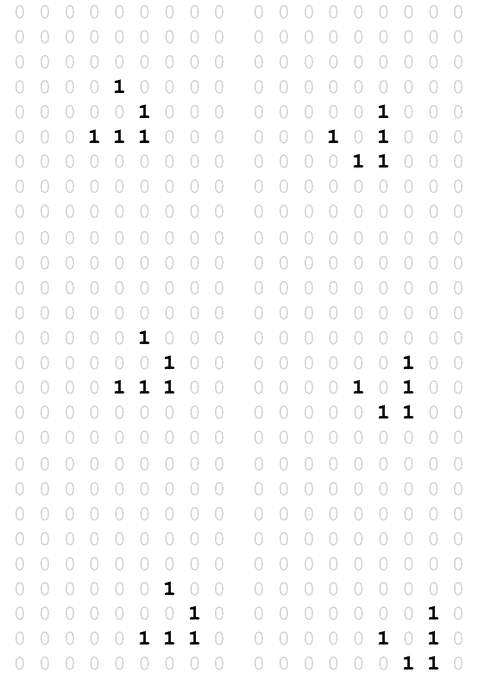
The other day I thought about that it would be nice to program Conway’s Game of Life in LaTeX and create an animated PDF output. You could say that implementing the Game of Life is pretty easy. It is. But not in LaTeX, at least not for me. After using LaTeX for years I still find it hard to understand some codes and especially writing programs in “pure LaTeX”.

Since I use PGF/TikZ fairly often I decided to use pgfmath for the implementation. Pretty soon I got stuck, I needed to assign values to array elements, and I didn’t know how to overcome this problem in LaTeX. So I decided to ask a question on TeX.SX. This is the point that things get interesting.

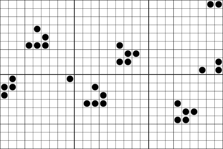
I asked a question with the title “Assign value to array element (PGF/TikZ)”, I also wrote that my aim was to program Conway’s Game of Life in LaTeX, and posted my initial code. Before long two answers came, and the question was renamed to “Programming Conway’s Game of Life in LaTeX”. The first answer implemented the Game of Life in LaTeX, the second implemented it in LuaTeX. I was stunned. Especially from the LaTeX implementation. I didn’t – and still don’t – understand the code. :) At the end I decided I should get acquainted with LuaTeX, and write my own solution in it:

Glider

1
2
3
4
5
6
7
8
9
10
11
12
13
14
15
16
17
18
19
20
21
22
23
24
25
26
27
28
29
30
31
32
33
34
35
36
37
38
39
40
41
42
43
44
45
46
47
48
49
50
51
52
53
54
55
56
57
58
59
60
61
62
63
64
65
66
67
68
69
70
71
72
73
74
75
76
77
78
79
80
81
82
83
84
85
86
87
88
89
90
91
92
93
94
95
96
97
98
99
100
101
102
103
104
105
106
107
108
109
110
111
112
113
114
115
116
117
118
119
120
121
122
123
124
125
126
127
128
129
130
131
132
133
134
135
136
137
138
139
140
141
142
143
144
145
146
147
148
149
150
151
152
153
154
155
156
157
158
159
160
\documentclass{article}
\usepackage[a0paper]{geometry}

\usepackage{luacode}
\usepackage{animate}
\usepackage{tikz}
\usepackage{xcolor}
\usepackage[active, tightpage]{preview}
\PreviewEnvironment{animateinline
}
%\PreviewEnvironment{tikzpicture}

\tikzset{%
    cellframe/.style={%
        minimum size=5mm,%
        draw,%
        fill=white,%
        fill opacity=0%
    }%
}

\tikzset{%
    alivecell/.style={%
        circle,%
        inner sep=0pt,%
        minimum size=4mm,%
        fill=black%
    }%
}

\setlength{\PreviewBorder}{5mm}

\begin{document}

\begin{luacode*}
    iterations = 36
   
    grid = {{0, 0, 0, 0, 0, 0, 0, 0, 0},
        {0, 0, 0, 0, 0, 0, 0, 0, 0},
        {0, 0, 0, 0, 0, 0, 0, 0, 0},
        {0, 0, 0, 0, 1, 0, 0, 0, 0},
        {0, 0, 0, 0, 0, 1, 0, 0, 0},
        {0, 0, 0, 1, 1, 1, 0, 0, 0},
        {0, 0, 0, 0, 0, 0, 0, 0, 0},
        {0, 0, 0, 0, 0, 0, 0, 0, 0},
        {0, 0, 0, 0, 0, 0, 0, 0, 0}}
\end{luacode*}

\begin{luacode*}
    function evolve(grid)
        local temp = {}
        local gridsize = #grid
       
        for i = 1, gridsize do
            temp[i] = {}
            for j = 1, gridsize do
                temp[i][j] = 0
            end
        end
       
        for i = 1, gridsize do
            for j = 1, gridsize do
               
                iminus = i - 1
                iplus = i + 1
                jminus = j - 1
                jplus = j + 1
               
                if iminus == 0 then
                    iminus = gridsize
                end
               
                if iplus == gridsize + 1 then
                    iplus = 1
                end
               
                if jminus == 0 then
                    jminus = gridsize
                end
               
                if jplus == gridsize + 1 then
                    jplus = 1
                end
               
                neighbourcount = grid[iminus][jminus] +
                    grid[iminus][j] +
                    grid[iminus][jplus] +
                    grid[i][jminus] +
                    grid[i][jplus] +
                    grid[iplus][jminus] +
                    grid[iplus][j] +
                    grid[iplus][jplus]
               
                if (grid[i][j] == 1 and (neighbourcount == 2 or neighbourcount == 3)) or (grid[i][j] == 0 and neighbourcount == 3) then
                    temp[i][j] = 1
                else
                    temp[i][j] = 0
                end
            end
        end
       
        return temp
    end
   
    function display(grid)
        local gridsize = #grid
       
       
        for i = 1, gridsize do
            for j = 1, gridsize do
                tex.sprint([[\node[cellframe] at (]])
                tex.sprint((i - 1) * 5)
                tex.sprint([[mm,]])
                tex.sprint(-((j - 1) * 5))
                tex.sprint([[mm){0};]])
               
                if grid[j][i] == 1 then
                    tex.sprint([[\node[alivecell] at (]])
                    tex.sprint((i - 1) * 5)
                    tex.sprint([[mm,]])
                    tex.sprint(-((j - 1) * 5))
                    tex.sprint([[mm){1};]])
                end
            end
        end
    end
   
    function animate(grid, iterations)
        for i = 1, iterations - 1 do
            display(grid)
            tex.sprint([[\newframe]])
            grid = evolve(grid)
        end
        display(grid)
    end
   
    function frames(grid, iterations)
        for i = 1, iterations - 1 do
            tex.sprint([[\begin{tikzpicture}]])
           
            display(grid)
            grid = evolve(grid)
           
            tex.sprint([[\end{tikzpicture}]])
            tex.sprint([[\clearpage]])
        end
       
        tex.sprint([[\begin{tikzpicture}]])
        display(grid)
        tex.sprint([[\end{tikzpicture}]])
    end
\end{luacode*}

\noindent\begin{animateinline}[autoplay,loop,
begin={\begin{tikzpicture}[scale=1
]},
end={\end{tikzpicture}}]{5}
    \luadirect{animate(grid, iterations)}
\end{animateinline
}
%\noindent\luadirect{frames(grid, iterations)}

\end{document}

Note: More information about my implementation is available in my answer on TeX.SX.

It turned out to be pretty easy to do this in LuaTeX, however I struggled with the modulus operator (%) and printing from Lua to TeX. Still it became a pretty nice solution, I think.

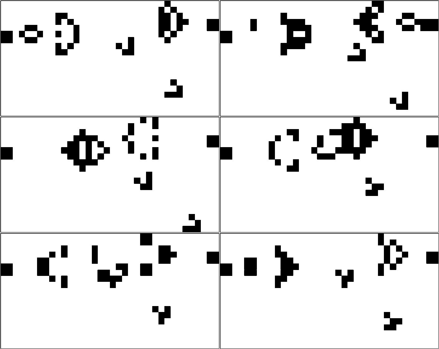
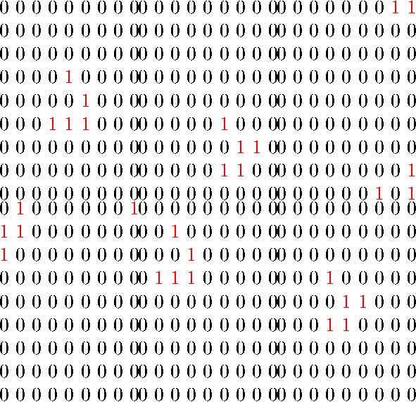
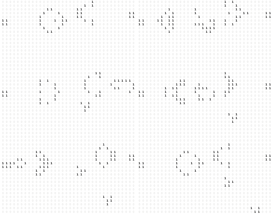
Last but not least I’m very grateful for the answers on my question. Here are some nice outputs of jfbu’s and JLDiaz’s answers (if you have a TeX.SX registration then please post an upvote on them because they are really great):

Gosper glider gun
Glider Glider
Gosper glider gun

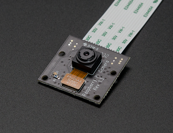
Múlt héten jött a hír, hogy rendelhető a Raspberry Pi-hez készített infravörös filter nélküli kamera a Pi NoIR.

Pi NoIR

Kép: adafruit industries blog

Azonnal rendeltem is egyet, majd írtam egy kommentet a HUP-ra, hogy én mire használom a kamera modult. trey-nek megtetszett, amit írtam, és írt is egy bejegyzést az ételdobozból és Raspberry Pi-ból készített time-lapse kamerámról.

Ennek eredményeképpen több megkeresést kaptam, hogy mennyibe kerül egy ilyen hordozható time-lapse kamerát összeállítani, illetve milyen szoftvereket használok, ezt próbálom most összefoglalni.

Szeretném megjegyezni, hogy az eddig elkészült felvételek még nincsenek kész, nincsenek megvágva, nincs rajtuk javítás stb. A cél egy hosszabb videó, vagy klip vagy ilyesmi készítése, és még nagyon az elején járok a dolognak.

Miből áll és mennyibe kerül?

A legegyszerűbb, ha felsorolom az alkatrészeket. (Az árak mellett feltüntettem, hogy milyen pénznemben értendők, mert pár dolgot külföldről rendeltem.)

  • Raspberry Pi Model B (rev2): 35 USD – Napi árfolyam kérdése, hogy Forintban mennyi.
  • Raspberry Pi Camera Board: 16.56 GBP – Napi árfolyam kérdése, hogy Forintban mennyi.
  • Wi-Fi USB adapter: ~2000–4000 HUF – Nagyon fontos, hogy elég legyen neki az az áram, amit az RPi közvetlenül le tud adni, különben powered hubot kellene használni.
  • SD kártya: ~5000+ HUF – Legalább 16 GB-os, class 10-es SD kártyát ajánlok, mert egy-egy fotózás alkalmával simán összejön 4–5 GB fotó.
  • 2 db 4-es AA elemtartó: ~150 HUF – Bármelyik elektronikai üzletben kapható.
  • kapcsoló: ~25 HUF – Nem emlékszem, hogy mennyibe került, 100 HUF alatt van az biztos.
  • 8 db 2500 mAh-ás 1,2 V-os NiMH akkumulátor: ~4000–8000 HUF – Az ár a márkától függ, nekem eléggé noname van. :)
  • ételdoboz: ~1000 HUF – Fontos, hogy légmentesen zárható legyen, így eső esetén nem folyik be a víz, a köd nem okoz gondot stb.
  • matt akrilfesték spray (fekete és fehér): ~2000 HUF – Az ételdoboz belülről feketére, kívülről fehérre van fújva. Belül fekete, hogy a különböző ledek fényét, villogását elnyelje nehogy becsillanjon a kamerába. Kívülről azért fehér, hogy visszaverje a fényt a melegedést elkerülendő.
  • UV szűrő: használtan ~500–1200 HUF
  • csavarok, alátétek: ~100 HUF
  • fényképezőgép állvány: Ehhez inkább nem írok árat (nekem korábbról volt már egy). Viszont nagyon fontos, hogy ha állvánnyal dolgozom, akkor legyen az állványon alul valami kampó, vagy más, hogy súly lehessen akasztani az aljára. Ugyanis az ételdoboz nagyobb, mint egy átlagos fényképezőgép, és a súlya még elemmel együtt is kicsi, ezért könnyen belekap a szél.
  • egyebek: maszkolószalag, szigetelőszalag, drót, forrasztópáka, forrasztóón, fenyőléc, laminált padlódarab. Utóbbi rögzíti a dobozt az állványra; úgy „faragtam”, hogy az állvány fejébe illeszkedjen. Ezek mind voltak itthon, árat nem tudok mondani.

Végösszeg: 28284 HUF (mindenből a legolcsóbbal és a mai USD és GBP árfolyammal számoltam).

Ebben nincs benne a fényképezőgép állvány, az itthon talált felhasznált anyagok, alkatrészek, sem az a készíttetett gyűrű, amelybe az UV szűrő illeszkedik. Nem gondoltam volna, hogy ennyit költöttem rá. Sőt, nekem 32 GB-os SD kártyám van, és nem is mindenből a legolcsóbb cucc, ráadásul több kamera modulom is van (NOiR is)… Szóval én valahol 50 ezer felett járok.

Szoftver

A legutóbb ennyit írtam a szoftverről:

A fényképezés mobiltelefonról vezérelhető:

  • A Pi egy USB-s WiFi modul hostapd és isc-dhcp-server segítségével szolgáltat hálózatot.
  • Egy SSH klienssel be lehet jelentkezni a Pi-re.
  • Egy egyszerű shell script a raspistill alkalmazással preview képet készít, amit netcat-tal browserbe továbbítva lehet megtekinteni.
  • Szintén egy shell scripttel lehet elindítani a fényképezést (5000 ms timeout).

Most ezt megpróbálom kicsit jobban kifejteni.

Az RPi-n „gyári” Raspbian fut, a fényképezéshez pedig a raspistill programot használom. Az SSH szerver szintén a „gyári”, a hostapd és az isc-dhcp-server konfigurációját pedig egyszerűen innen puskáztam:

A használt scriptek pedig letölthetők:

Nincs bennük semmi magic. A fényképezésre külön scriptek vannak (capture-*.sh), amelyekben csak a két kép közötti timeout az eltérő. Preview-t pedig a preview.sh scripttel lehet készíteni. Ez utóbbi ahhoz kell, hogy a fényképezés elindítása előtt rendesen be lehessen állítani az állványt és a kamerát.

Képek feldolgozása

A képek bizgetéséhez ImageMagick-et használok. Itt egy szokásos, csak croppoláshoz és átméretezéshez használt parancs, ami végigmegy a megadott könyvtárban található összes jpg fájlon:

mogrify -gravity northwest -crop 2592x1458+0+308 +repage -resize 1920x -format png \
-path /media/szantaii/Tibor/capture/cap1_processed/ /media/szantaii/Tibor/capture/cap1/*.jpg

Egy másik paraméterezéssel már a színeket is állítgattam (ennek az eredménye látható a poszt végén):

mogrify -gravity northwest -contrast -contrast -color-matrix "1.2 -0.1 -0.1 -0.1 1.2 -0.1 -0.1 -0.1 1.2" \
-crop 2592x1458+0+243 +repage -resize 1920x -format png \
-path /media/szantaii/Tibor/capture/cap28_processed_enhanced/ /media/szantaii/Tibor/cap28/*.jpg

Az utolsó példában pedig egy 1,6 fokos forgatás, vágás és átméretezés van:

mogrity -gravity center -background "rgb(0,255,0)" -rotate "1.60" +repage -gravity northwest \
-crop 2446x1376+54+176 +repage -resize 1920x -format png \
-path /media/szantaii/Tibor/capture/cap30_processed/ /media/szantaii/Tibor/capture/cap30/*.jpg

A felsoroltakon kívül még az ImageMagick -sigmoidal-contrast operátorával „játszottam”.

Az eddigi parancsokkal csak a képeket dolgoztam fel. A képekből a videót pedig FFmpeg-gel fűzöm össze. A végeredményt 30 és 60 fps-be is ki szoktam renderelni, hogy lássam melyik néz ki jobban. A 30 és a 60 fps generálása között csak annyi a különbség, hogy az FFmpeg-nek meg kell adni, hogyan értelmezze a bemenetként szolgáló képeket, vagyis az -r kapcsoló után 30-at vagy 60-at kell írni.

ffmpeg -r 30 -i %06d.png -vcodec libx264 -vprofile high444 -vlevel 4.2 -pix_fmt yuv420p ~/Desktop/test_30fps.mp4
ffmpeg -r 60 -i %06d.png -vcodec libx264 -vprofile high444 -vlevel 4.2 -pix_fmt yuv420p ~/Desktop/test_60fps.mp4

https://vimeo.com/77900126

Hirtelen (az elmúlt másfél órában) ennyi jutott eszembe.